| University of Bielefeld - Faculty of technology | |
|---|---|
|
Networks and distributed Systems
Research group of Prof. Peter B. Ladkin, Ph.D. |
|
| Back to Abstracts of References and Incidents | Back to Root |
| This page was copied from: http://www.open.gov.uk/aaib/gobme/a27.htm | |
Appendix 2.7
Engine instrumentation
Layout
The design of engine instrumentation
on multi-engined aircraft is inevitably a matter of compromise.
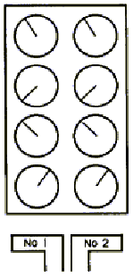
The conventional and ergonomically accepted layout is for all
instruments associated with a particular engine to be organised
in a column, and for all instruments of the same type to be organised
in a row. It is, moreover, clearly preferable for each column
of instruments to be associated spatially with the throttle of
the appropriate engine. This is the basic layout illustrated in
Figure 1 and the desirability of using such a layout for the primary
engine instruments is clear. Secondary engine information is not
required on the front panel of the flight deck in those aircraft
with three man crews, and the ideal layout of front panel engine
instrumentation described above may thus he adopted.

FIGURE 1
If the aircraft is provided with only
two crew members, however, then the secondary engine instruments
must be accommodated on the front panel as well. They cannot be
accommodated by extending the height of the columns since panel
height precludes such an option if the instruments are to be large
enough to remain legible.
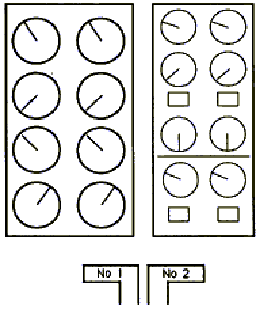
If the instruments are all to be located
on the front panel, two possibilities are apparent. The first
is to mount the secondary instruments to one side of the primary
instruments as in Figure 2.
| Primary | Secondary |
| Instruments | Instruments |
| Nol No2 | Nol No2 |

FIGURE 2
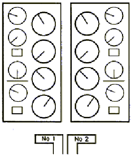
The second is to split the secondary
instruments and mount them outboard of their respective primary
instruments, as in Figure 3.
| No 1 engine | No 2 engine |

FIGURE 3
The advantage of the layout in Figure
3 is that the instruments for a given engine are all mounted together
and are, if not spatially, at least cognitively, aligned with
their associated power levers. This is achieved at the price of
splitting the secondary instruments apart, with the associated
possibility of disparate secondary readings going undetected.
Figure 2 achieves the goal of keeping
the instruments paired together, and thus maximises the chances
of disparate readings being detected, but does so at the price
of splitting up the instruments associated with a given engine,
and of losing the advantage of having all instruments cognitively
aligned with their corresponding throttle levers.
Thus, Figure 3 could fairly be judged
to maximise the probability that a given failure will be correctly
identified by the crew as belonging to a given engine, at the
possible cost of less efficient error detection on the secondary
instruments, whereas Figure 2 may be judged as maximising the
probability that disparate readings will be detected at the cost
of degrading the probability that this detected failure will be
associated by the crew with the correct engine.
The design of the EIS
The layout of the EIS in the Boeing
737 Series 300/400 conforms to Figure 2, which has been widely
used without apparent difficulty in many two-engined, two-pilot
aircraft. The illumination of the display, however, might aggravate
the problem of perceived misalignment of the instruments with
their respective throttles. On the hybrid instruments (LED counters
with electromechanical pointers) fitted to other aircraft of this
type, the faces of the instruments needed to be lit from in front
to show the pointers, dials and scale marks. Such lighting does
not, of course, illuminate only the legends and pointers on the
instruments but also the general structure and limits of the display,
so that the instruments could be argued to be viewed within a
structured visual frame. In the EIS display, all symbology is
edge-lit and set against a heavily constrasting background which,
in an aircraft at night will be, to all intents and purposes,
black. This may have the effect of enhancing the extent to which
the instruments are seen as a single display rather than as two
separate displays, and may degrade the extent to which deviant
readings in, say columns 1 and 3 of the matrix could readily he
associated with the No 1 engine.
The next most obvious and important
change made between the hybrid system and the EIS is that the
full-radius mechanical pointers have been changed to short LED
pointers moving round the outsides of their scales. The mechanical
pointers were relatively large, white and clearly linear devices,
and their orientation on the display was immediately apparent.
Not only was the absolute orientation of each pointer apparent
but (and perhaps more importantly) it was readily apparent whether
the pointers of each pair of instruments were parallel with one
another. The pointers on the LED display are much shorter than
the mechanical pointers, they are the same colour as the LED counters
and they move in steps. They are much less conspicuous than the
mechanical pointers, acting more as scale markers, and providing
less immediate directional information. They are thus less well
able to give the comparative information provided by the strong
cue of parallelism of the mechanical pointers. This comparative
information can be obtained with certainty only by interrogating
each instrument to see if the LED pointers of each pair are at
the same points on the scale or by comparing the readings of the
pairs of counters.
Evaluatton and testing
The entire function of any display
on a flight deck is to transfer information from the aircraft
to the pilot, and to do so in the way that will cause the pilot
least workload and will be least likely to be interpreted wrongly.
Although some principles, such as those discussed above, guide
the design of displays, the only way of evaluating the adequacy
of a display is by experiment and trial. It is therefore important
that before any display is put into service, it is subjected not
just to some form of acceptability judgement by company pilots,
but to a structured assessment using average line pilots. Indeed,
it could he argued that such assessments should he conducted using
the least able pilots who are ever likely to use the display.
A display similar to the EIS was developed
by Smith's Industries for use on the McDonnell Douglas MD88. It
was held to differ from an earlier display which employed mechanical
pointers, in that the colour coding of some dials was changed.
The new display was evaluated by pilots employed by McDonnell
Douglas and the Federal Aviation Administration (FAA). The evaluation
was held to show that the new display provided clearly readable
and interpretable information to the flight crew, showed whether
the current state of power plant operation was normal or abnormal,
indicated the engine maximum/minimum safe operating range and
showed whether the system(s) operation was being accomplished
in a safe manner. These results were used by McDonnell Douglas
to demonstrate to the FAA the acceptability of the new display
as an equivalent means of compliance with current airworthiness
regulations.
The EIS for the Boeing 737 was designed
to represent a minimum change from the previous hybrid display
and, accordingly, it was type certified by both the FAA and the
CAA as fit for its purpose. The counters remained identical in
size and colour but the dials of all instruments were reduced
in size. The pointers were reduced in length by approximately
two-thirds and placed on the outsides of the dials but the circumference
swept by the needle tips (ie the instrument 'size') remained the
same. The EIS display was deemed to have sufficient communality
with the hybrid display to circumvent the need for pilots to be
separately rated for EIS-equipped models. It was tested for proper
operation, compatibility and freedom from electrical interference
but it was not evaluated for its efficiency in imparting information
to pilots.
Although the desire for communality
is understandable, because a number of other factors were changed
between the hybrid and the EIS displays, the apparent benefit
of keeping size constant may have been offset or even negated
by varying others such as illumination, contrast and pointer size.
The desire to maintain consistency of di splay format while introducing
new technology was responsible for the reduction in pointer size
and con spicuity, and exemplifies a general problem. LED and CRT
displays possess potential advantages over old technology instrumentation
that may be exploited only if the display is designed afresh to
exploit them. If a new technology display is designed simply to
mimic the appearance of its precursors it may well fall into what
is sometimes referred to as the 'electric horse' trap; the strengths
of the old system are discarded because they cannot be duplicated,
and the potential strengths of the new system are not exploited.
Full length pointers cannot he represented on the LED system because
the packing density of central LEDs cannot be achieved, and because
symbology cannot be overlaid, and a potentially less satisfactory
pointer is substituted.
It is reiterated that the general effectiveness
of any new display may be judged only by trial and experiment,
but even then some criterion of acceptability must be adopted.
An obvious criterion in the case of engine instrumentation is
that the new display should not prove less satisfactory to those
pilots who use it than the display it replaces. When the EIS was
introduced for use on the Boeing 737 no such tests were carried
out.
Conclusions
Although there seems to be no question
that the EIS display on the Boeing 737 provides accurate and reliable
information to the crew, the overall layout of the displays, and
the detailed implications of small LED pointers rather than the
larger mechanical ones, and of edge-lit rather than reflective
symbology do appear to require further consideration. These factors
should not be ignored and the suitability of such new displays
for use by airline pilots should be evaluated before they are
brought into use.
| This page was copied from: | http://www.open.gov.uk/aaib/gobme/a27.htm | ||
COPY!
| |||